

How great would it be if you could control that and make it happen anytime you want? So, a few years ago, I learned about Tesla Coils, an air core electrical resonant transformer, invented by Nikola Tesla at the end of the XIX century, able to generate high voltages at high frequencies, resulting in electrical discharges just like small lightning. From that moment I knew I had to build my own Tesla Coil.
Back in 2010, I started to seriously think about it, plus, one of my University teachers was encouraging me on making one, so I got together with two great friends of mine, Micael Martins and Jarred Briscoe, and we started planning it.
First things first, what type of Tesla Coil should we build? There are many different variations: first you have the Spark Gap Tesla Coils or SGTC, as the name says, these are based on a spark gap switching mechanism, they are more simple to build but require a high voltage power supply; then there are the Solid State Tesla Coils or SSTC which rely on transistors such as MOSFETs or IGBTs to handle the switching part, these are the ones that can be turned into musical Tesla Coils, however they might be quite complex to design; and then there are others like the Vacuum Tube Tesla Coils or VTTC which use the good old vacuum tubes as a mean of generating the oscillation needed for the circuit.
Since this was our first one we thought it was a good idea to choose something simple and cheap, so we opted for the spark gap Tesla Coil. There are some different variations of the schematic but we will follow this simple one:

Probably the most expensive and hardest part to find, is the high voltage power supply, which is also the most important one, because ultimately, the maximum spark length you can generate is directly related to the power of the supply. The most common choice here is a Neon Sign Transformer also known as NST, because of their low size and weight compared to other alternatives like the pole pig oily transformers for example, which are extremely big and heavy, and are harder to obtain. The power transformer should have a voltage between 9kV and 15kV.
For us this part was easy because I already had a NST laying around at home from an old neon sign. This transformer we're using has 10kV and 30mA:

Next, with the characteristics of the transformer, it must be determined the value of the primary tank capacitor. Every half cycle of the mains supply, in my case every 10 ms since the frequency in Portugal is 50Hz, the spark gap will fire and transfer the energy from the primary capacitor to the primary coil, which means that the capacitor must be able to fully recharge every half cycle as well. So the appropriated capacity must be calculated.
Using Ohm's law for alternate current with the transformer specifications we get:
When I started checking prices for smaller capacitors I discovered that even if they weren't expensive, it would still cost me around 100€ because I would be needing a lot of them. But that was unacceptable for me, I was aiming for something cheap so I couldn't spend all that money just for the capacitor.
So I started looking for alternatives, then I figured, since I won't buy a capacitor, I can build it completely from scratch. Again, there are always different options, in this case, there are 2 easy ways of building a capacitor from raw materials. One way is using intercalated layers of a conductive material and an isolator, which is known as a plate capacitor. The other way is using the principle of the Leyden Jar, the original form of the capacitor, which can be easily reproduced with glass bottles. We eventually chose the second option and started making a bottle capacitor.
All we needed was a plastic bucket (avoid black plastic because they can have conductive properties), glass bottles, water, salt, oil (mineral is preferred but vegetable also works, although it might be starting to smell like fries), a few wires, hex bolts and nuts.
We heated up the water, started pouring salt and mixing it until it reached the saturation point, this is, until it couldn't dissolve salt anymore. The salt water will be the conductive electrode for both sides of the capacitor, the salt is added to make sure the water is highly conductive, and the heating is just to speed up the process of dissolving the salt. Then the salty water is poured inside the glass bottles until a certain point. The rest of the bottle is filled up with oil like it shows in the following image:


To have an idea of how many bottles you'll need, you can consider that a normal 330 ml bottle will give about 1nF of capacity, depending of course, on the water/oil proportion you'll put in. Since I'm aiming at 9.5 nF, this means I'll probably be needing something like 9 to 10 bottles, but this is always a rough estimate, so you better have more bottles ready.
But I wanted to make sure of it, so I started calculating. For this you'll need the formula for capacitance, which relates the electric capacity with the area of the electrode plates, the distance between them, and the vacuum and relative permittivity. The vacuum permittivity is a constant equal to 8.854x10^-12 but the relative permittivity varies with the dielectric material. Usually for glass, this value is somewhere between 3.7 and 10. For the bottles I was using I was able to determine, through some practical experiments, that the relative permittivity was approximately 9. But there are many data tables you can use for reference.
First you need to calculate the area of electrode, which can be calculated by multiplying the perimeter of the bottle by the height of the water inside:

Here are the bottles with the solution, ready to be put inside the bucket:


Again, since we were aiming at a simple and cheap project, we opted for the static gap. Usually they are separated into smaller air gaps all connected in series, which has the advantage of supporting more power, since it can dissipate more heat, and also allows for easier tuning when adjusting the distance between the electrodes, because it becomes a matter of choosing to which electrode the connection is made. Sometimes a ventilation system is also added to the spark gap, to help reduce the heating.
Considering that we wanted something simple but effective, we decided to use a single air gap, besides, our transformer was not that powerful, and since we would be using bolts as electrodes, they would be able to dissipate the heat fairly well, even without ventilation. The distance between the electrodes would also be easy to adjust because we were using bolts, so by rotating a bit more or less, would also vary the distance as well. The usual distance is around 6 mm for a 10 kV NST.
Here is our simple spark gap:

And with this, the primary circuit is almost finished, the primary coil is the only part missing, but to be able to design this coil properly, we must first design the entire secondary circuit, which is composed by the secondary coil and the discharge terminal.
First let's focus on the secondary coil. The most common material for this part is a PVC pipe, fortunately I already had a few of these at home:


Now we need to know the inductance of the coil in order to later determine the resonant frequency of the secondary circuit. For this we can use the inductance formula for cylindrical coils:


For our coil, the LCR meter showed an inductance of 7.48 mH, again, remarkably close to the theoretic approach, and a self capacitance of 8.35 pF.
And now the discharge terminal. There are 2 commonly used shapes for this part, a sphere and a torus or toroid. This terminal acts as a capacitor, and together with the previous coil, they form the secondary LC circuit. There are not many guidelines when building this part of the project, but basically the bigger it is, the more capacitance it will have.
For this we used 2 metal discs, a threaded rod, aluminium ducting, nuts and aluminium tape:


Now that we have the secondary coil and the toroid, the secondary circuit is complete. This is actually an LC circuit, so it will have a resonant frequency:

The resonant frequency of an LC circuit is given by:


The primary coil is a good place for fine tuning the Tesla Coil after its construction is complete. No matter how many calculations have been made, there will always be differences from what you've designed and what you've ultimately built. For this reason it is a good idea to make sure the primary coil will have some extra turns, in case the math is a little off.
To do this, you'll need to try some different values. In my case, I'm using a 6.5 mm copper tubing, the inner diameter of the coil will be around 115 mm, and the spacing between turns is also 6.5 mm:
.png)
First, the width of the coil:


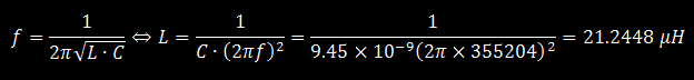
By using 11 turns with these characteristics, the primary coil will have a total of 30.1938 μH, well above the 21.2448 μH needed to generate the resonant frequency. This should be more than enough to adjust any discrepancies that may occur.
However, I need to know exactly in which turn I'll have the inductance I want, to place the outer terminal of the coil. To do this I must recalculate the coil by testing with a different number of turns, until it reaches values close to 21 μH. To assist with these repetitive calculations I created a spreadsheet with all these formulas to automate the process. Another option is going to the website DeepFriedNeon, which has a few good online calculators you can use, for all the parts of a Tesla Coil, as well as some construction guidelines. It's particularly useful for the primary coil.
By testing with a different number of turns, I can observe that if I use 9, I will obtain 19.25 μH and if I use 10 turns I will get 24.34 μH, this means that the value of 21.2448 μH which I need for the resonant frequency, is somewhere between turn 9 and 10 of my primary coil.
To build the flat coil we used 6.5 mm diameter copper tubing and some PVC U profiles. We drilled a series of 7 mm holes for the copper tubing, onto the PVC profiles, they would be the support of the coil. The copper tubing was then guided through these holes. Here is the final result:

With the primary coil finished, it was time to start building the main structure for the Tesla Coil. For this we used 2 pieces of wood to create 2 bases on top of each other, one bellow for the NST transformer and the spark gap, and one on the top for the primary and secondary coil.


The primary coil was then fixed onto the top base:


I have neither of these filters, however, since I needed a connector for the mains supply and I used one from an old ATX power supply, it already had a small filter integrated. It is not exactly dimensioned for this application, but I thought it wouldn't hurt to have it on the circuit. Still better than nothing:

Now the other connections. The mains supply come through this AC filter and then goes directly to the primary of the NST transformer.
After the NST, all wiring mush be made with high voltage cables. The high voltage output from the NST is connected in parallel with the spark gap:


Although calculations were made, there are always differences to what happens in real life, there are too many variables that are harder to control, what this means is that, no matter what results you got in paper, you'll always need to adjust some parameters to optimize the physical results.
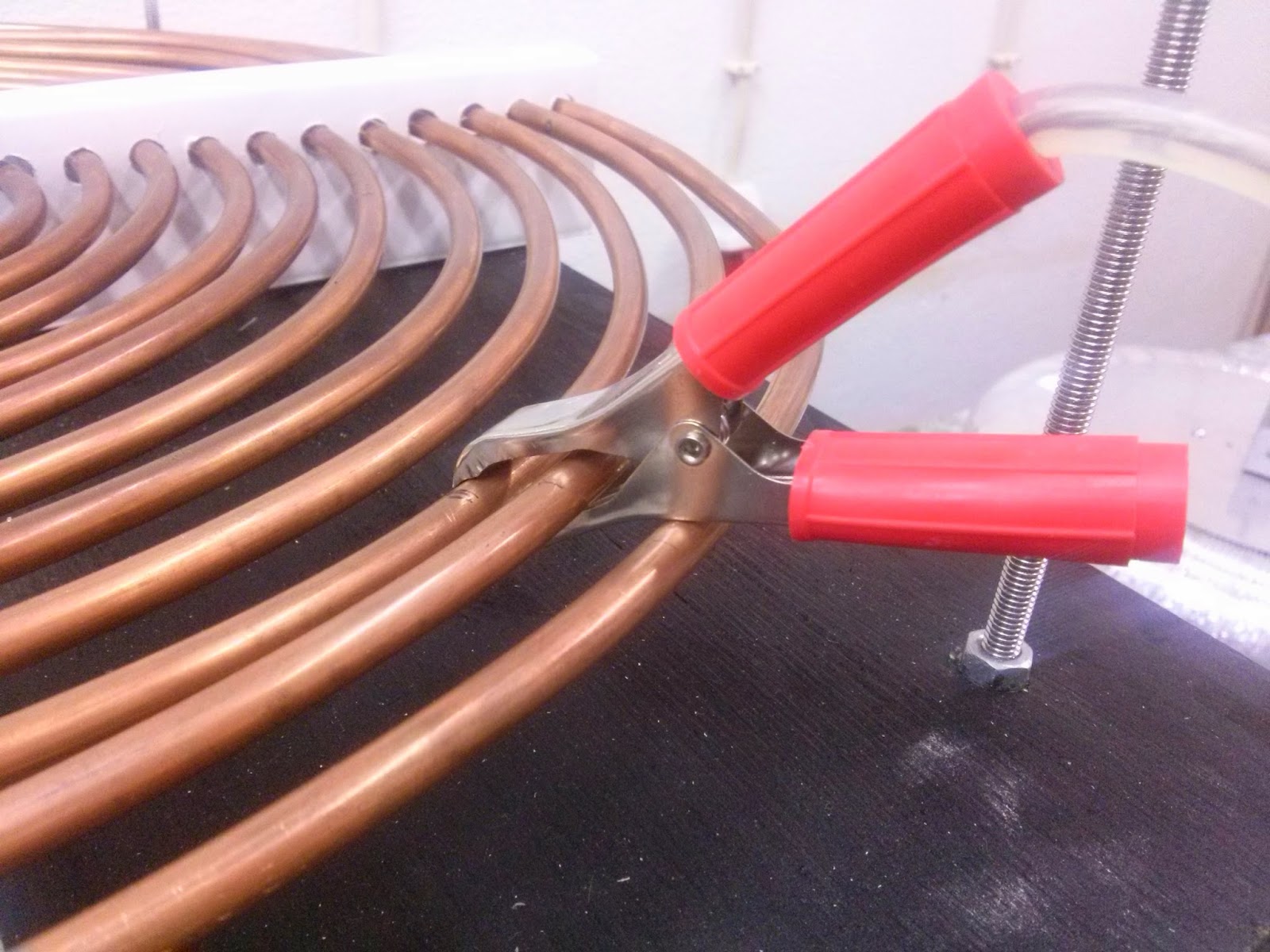
In our case it was mostly the distance of the spark gap and the turns on the primary coil. The spark gap would stop firing sometimes, which we then discovered it was because the electrodes were too far apart from each other, so we put them a bit closer. Now the primary coil was based on a try and error approach, we knew from the calculations in which turn we should get the optimal results, so by moving the crocodile clip a bit right or a bit left, it would change the inductance of the coil and ultimately the resonant frequency.
Eventually we got it better, now it would produce discharges into the air without the rod:

Eventually we started trying other things, for example adding a metal rod on top of the toroid:


Here is a short video of the Coil's discharges into the rod:
But of course we wouldn't stop there, one of the funniest and most interesting things to do with a Tesla Coil is to light up fluorescent tubes just by being in the proximity of the Coil. A great example of wireless transmission of energy:

Fortunately we were able to finish the project before Lisbon Mini Maker Faire, so we took it there:


Still at the Maker Faire, here are 2 friends of mine playing with fluorescent tubes near the Tesla Coil. It kinda looks like a Jedi fight:
There were plenty of visitors interested in the Tesla Coil:
 The project even got featured on a technology program for a Portuguese TV channel:
The Tesla Coil was also awarded a prize at Maker Faire, as an outstanding project!
Still, I know that the project can be even more optimised, but that's for another time.
Still, I know that the project can be even more optimised, but that's for another time.
Hi.
ReplyDeleteI built the same with 10kv 30ma may.
But the spark gap didn't fired at all.
I used an electronic nag.
Is there any problem with electronic may?
What do you mean by electronic nag?
Delete